| |
|
|||||||
|
|
||||||||
|
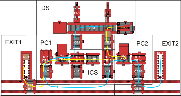
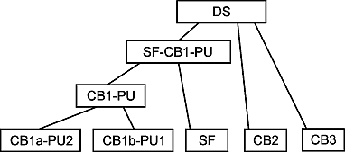
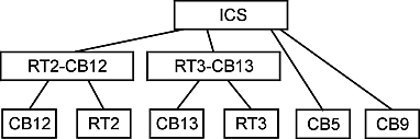
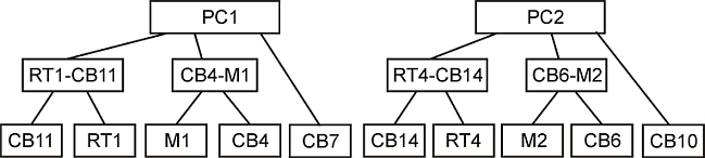
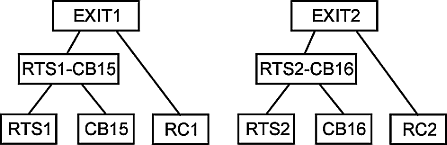
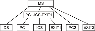
Observer Based Hierarchical DesignIn this case study, we apply the observer based design method to our Fischertechnik laboratory model of a manufacturing system. It consists of a total number of 28 components, including 16 conveyor belts (CB), 4 rotary tables (RT), 2 pushers (P), one stack feeder (SF), one rail transport system (RTS) with two rail cars, 2 production machines (M) and 2 roll conveyors (RC); the overall layout is given in the below figure. Each component is modeled as finite automata with a state counts ranging from 3 to 34 states. The parallel composition of all components has an estimate state count of 10^24. Starting from the automata models we first compute local supervisors that ensure the desired behavior of each component. Then, the coordination among the components is accomplished by a multi-level hierarchical design: System components are successively abstracted and composed in order to obtain system models with a moderate state space that are suitable for the design of coordinating supervisors. In the abstraction process, certain conditions such as "observer" conditions for the nonblocking control ([O1],[O3]) or "local control consistency" for the maximal permissive control ([O2]) have to be fulfilled. As the global system specification, the two workpiece paths that are shown in the figure below are desired. The first path (blue) requires that workpieces are first processed by machine M1 before passing machine M2 and reaching the right-hand roll conveyor. The second path (yellow) concerns workpieces that are first handled by machine M2 and then move to machine M1 and the left-hand roll conveyor. In addition, it is desired that always two workpieces of the first type are followed by one workpiece of the second type. For a hierarchical design, the manufacturing system is divided into 6 modules that are first individually controlled and finally put together to form the overall system. This division is illustrated in the figure above. The first module is the distribution system (DS) as depicted in the above figure. Its purpose is to distribute workpieces that enter the system from the stack feeder SF. In our example synthesis, it is desired that always one workpiece has to be pushed by PU1 after two workpieces have been pushed by PU1. The supervisor design for the DS is performed in 4 hierarchical levels that are shown in the figure below. The interconnection system (ICS) provides a connection between the production cells on the left-hand and on the right-hand side of the laboratory model. Its desired functionality comprises workpiece paths from PU1 or CB9 to M2, from PU2 to M1 and from M2 to M1. The associated supervisor design is done in 3 hierarchical levels as illustrated in the figure below. The two production cells PC1 and PC2 constitute further separate modules of the laboratory model. In both cases, it is desired that workpieces that enter the respective production cell are first processed and then transported to their next destination. In the case of PC1, all workpieces enter from CB12 and are carried to CB15 on the RTS. For PC2, all workpieces arrive from CB13, whereas they are delivered either back to the ICS or forward to CB16 on the RTS. A hierarchical design with 3 levels is suitable for the two production cells. Finally, the exit systems EXIT1 and EXIT2 are mostly used for the storage of the processed workpieces. EXIT2 simply transports workpieces from PC2 to the associated right-hand roll conveyor. Conversely, EXIT1 takes workpieces from PC1 to the left-hand roll conveyor. In addition, EXIT1 is able to deliver workpieces from PC1 to PC2. The supervisor design for the exit systems has 3 hierarchical levels. In order to coordinate the operation of the separate modules, a hierarchical design with 2 additional levels is performed (see figure below). First, the modules PC1, ICS and EXIT1 are coordinated before an overall coordinating controller ensures the specified system behavior without any blocking. Together, the resulting supervisor hierarchy comprises 28 supervisors for the local components and 18 high-level supervisors.
Supervisor HierarchyThe component models, the specifications and the resulting supervisor hierarchy can be inspected in the below directory tree. All relevant files are distributed with the current version of the libFAUDES observer plug-in, incl. luafaudes-scripts to perform the overall synthesis procedure. With a recent version of libFAUDES installed, you can run the synthesis procedure from the observer plug-in tutorial directory. With graph output disabled, the overall synthesis takes about 3 seconds on a standard PC (dated 2010). ~/$ cd libfaudes/plugins/observer/tutorial ~/$ ../../../bin/luafaudes op_fsmsynth_ms.lua State count of the SF abstraction: 1 State count of the CB2 abstraction: 2 State count of the CB3 abstraction: 2 State count of the CB1PU abstraction: 7 State count of the combined CB!Pu and SF abstraction: 3 State count of the DS abstraction: 6 Accumulated state count of the DS supervisors 226 State count of CB11 abstraction: 4 State count of RT1 abstraction: 4 State count of RT1-CB11 abstraction: 2 State count of CB4 abstraction: 4 State count of MH1D1 abstraction: 4 State count of CB4-MH1D1 abstraction: 2 State count of CB7 abstraction: 2 State count of PC1 abstraction: 3 Accumulated state count of the PC1 supervisors: 83 State count of CB14 abstraction: 4 State count of RT4 abstraction: 4 State count of RT4-CB14 abstraction: 2 State count of CB6 abstraction: 4 State count of MH2D2 abstraction: 4 State count of CB6-MH2D2 abstraction: 2 State count of CB10 abstraction: 2 State count of PC2 abstraction: 5 Accumulated state count of the PC2 supervisors: 101 State count of the CB15 abstraction: 4 State count of the RTS1 abstraction: 11 State count of the RTS1-CB15 abstraction: 4 State count of the RC1 abstraction: 1 State count of the EXIT1 abstraction: 3 Accumulated state count of the EXIT1 supervisors: 70 State count of CB16 abstraction: 4 State count of RTS2 abstraction: 6 State count of RTS2-CB16 abstraction: 2 State count of RC2 abstraction: 1 State count of EXIT2 abstraction: 1 Accumulated state count of the EXIT2 supervisors: 48 State count of CB5 abstraction: 2 State count of CB9 abstraction: 2 State count of CB12 abstraction: 4 State count of RT2 abstraction: 4 State count of RT2-CB12 abstraction: 3 State count of CB13 abstraction: 11 State count of RT3 abstraction: 4 State count of RT3-CB13 abstraction: 4 State count of ICS abstraction: 30 Accumulated state count of the ICS supervisors: 181 State count of PC1-EXIT1-ICS abstraction: 205 Accumulated state count of the PC1-EXIT1-ICS supervisors: 594 State count of the MS supervisor: 2762 libFAUDES 2.34g --- 2026.04.28 --- with "omegaaut-synthesis-observer-observability-diagnosis-hiosys-iosystem-multitasking-coordinationcontrol-timed-simulator-iodevice-priorities-luabindings-hybrid-example-pybindings" |